The kuttyPy Hardware
The schematic is relatively simple. It contains the following parts :
- An ATMEGA32 processor
- A USB-Serial bridge IC
- A common cathode RGB LED with R,G,B pins connected to PB3, PD5, PD7 (All 3 have PWM)
- Some components such as crystals and capacitors
- Each port is cleanly broken out into 10 pin berg sockets(8x I/O pins, 5V, GND), and labelled properly
- There is also a PCRST jumper which can be removed if the bootloader is no longer needed.
Schematic

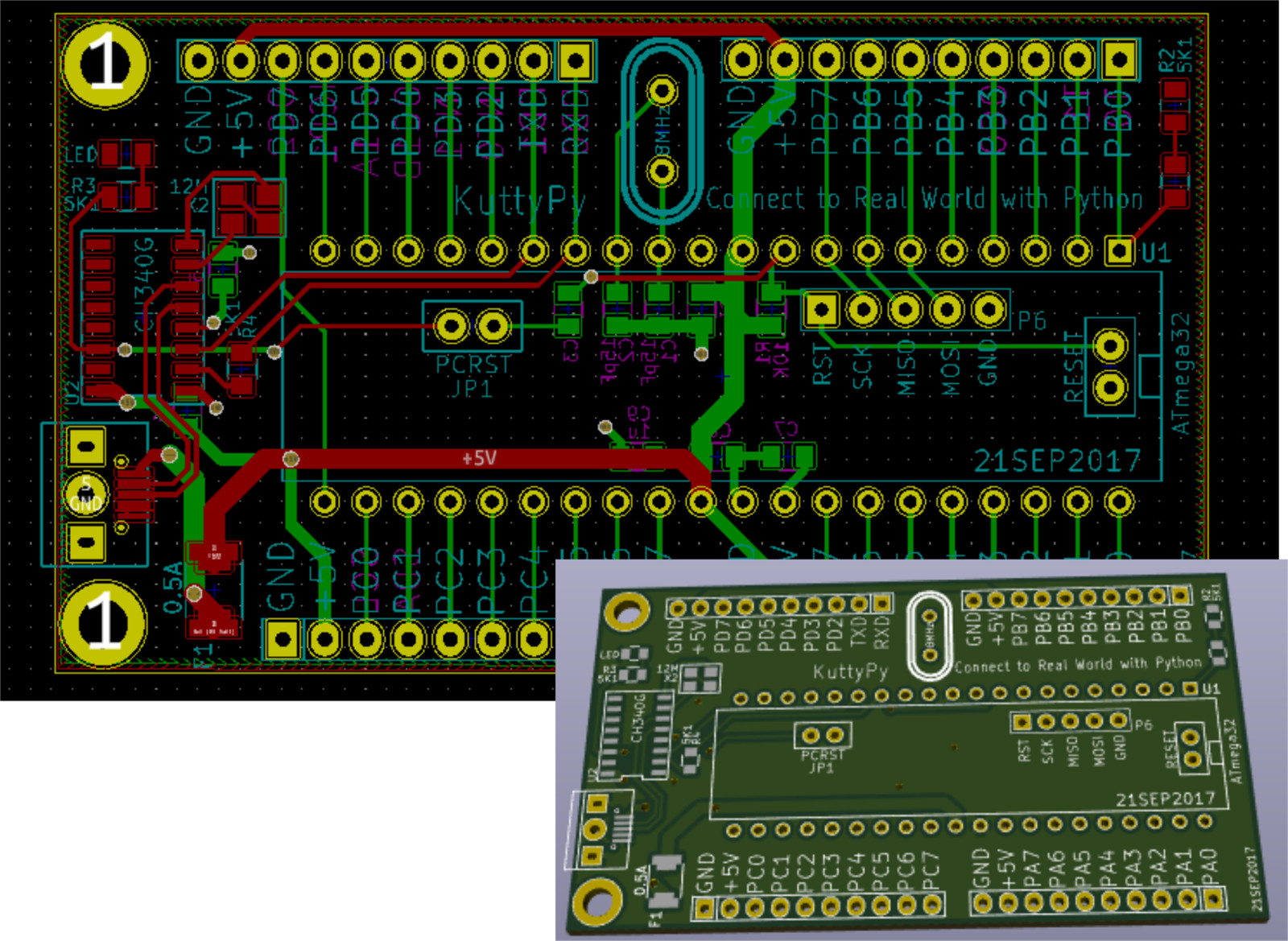
Layout
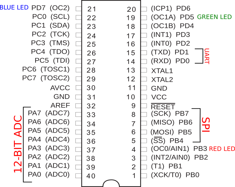
Pinout diagram
Pinout diagram for ATMEGA32 + KuttyPy specific connections
Hardware designs are licensed under OHL, and KiCAD files can be downloaded from the creators