The Graphical Interface
Getting off the ground
Playgroundtab- Connect the KuttyPy hardware on any USB port, and launch the software
- All pins are input during launch, and their logic level is indicated by red/green squares next to the pin numbers in the software
- Each pin can be converted from Input to Output by clicking on the
INPUTbutton next to it. - Some pins may have additional functionality as well, such as
PWM,ADC, andCNTR
Registerstab- You can select microcontroller registers, and toggle bits manually
Python Codetab- write Python code to control the hardware, and use python’s modules to visualize and analyze
The KuttyPy Python software
Software Features
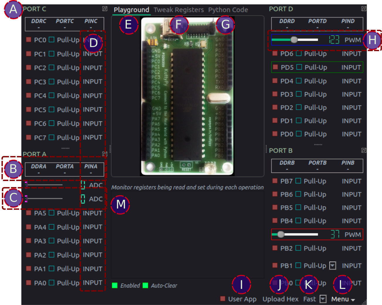
Let’s take a quick look at the various parts:
APORT Docks : The hardware has segregated all 4 PORTs of 8 pins each into 4 separate pin headers . The software has also segregated them in a similar fashion.BPORT Register values: The current value of the registers associated with the I/O functions of the ports are shown here. Click on them to cycle between display modes such as hex, decimal, or binary. Pin states are best understood when viewed in binary mode.- DDRx : Each bit of this register represents the corresponding pin of the 8-bit PORT. bit value 1 implies output functionality, and 0 means the pin is a high impedance input
- PORTx: In output mode, the corresponding pins are connected to 5 volt if the corresponding bit is 1, or 0 Volts(Ground) if it is 0. In input mode, if the bit is high, an internal pull-up is enabled to prevent the input from being in an undefined state.
- PINx: This register stores the value of the inputs. If an input pin is connected to the supply voltage, the corresponding bit will have value 1, otherwise 0.
CADC monitor: The pins on PORTA have a 10 bit ADC included. The ADC value which lies between 0 and 1023 is shown on an LCD display as well as a slider. Click on the LCD display to change the acquisition mode to differential or amplified.DMonitor type: Click to change between Input/Output/ADC/PWM/Counter depending on function availabilityEPlayground : Automatic monitoring and control of I/O pinsFTweak registers : Manually specify registers to read or write, and also the sequence in which this should be done.GPython code : Write python code for automated tasksHPWM : Set the PWM duty cycle [ Available only on PD5,PD7, PB3 ].IUser App : The kuttypy hardware can also contain a user uploaded hex file. By default this is an LED fading app which also continuously dumps letters into the serial port. Click this button to switch execution to the use app, and freeze monitoring utilities. The log window specified by (M) turns into a serial monitor. Uncheck to restore monitoring.JUpload a hex file compiled with AVR-GCC for ATMEGA32KSpeed: Change the refresh rate of the monitoring utilityLMenu : Save the window as an svg file, change the theme, control stepper motors, and more…MLog window : Show the registers being read/written in during operation of the monitoring utility. This also launches an analog gauge which displays the value of each input character. Useful for user code which transmits parameters via the serial port.